2017年4月11日星期二

Paging System For Restaurant(Use a micro DC motor)

It’s the weekend and you have plans for an elaborate dinner at one of the best restaurants in the city. However, due to your busy schedule, you fail to reserve a table. And then when you walk in, its jam packed. Anyways, the hostess writes down your name and asks you to wait till your name is called out. You are waiting and walking around the restaurant when suddenly, your name is hollered over a megaphone.
You rush to the hostess but your name is hollered again and again till you reach the spot. You get the table alright, but you wonder whatever happened to good old privacy and discreetness. On the other hand, if the restaurant had a paging system in place, it would have been far easier and comfortable for both parties.
A Restaurant paging system is a simple to use device which utilizes the paging technology with a micro DC motor. As a guest walks into a restaurant and finds the tables occupied, he is handed over a pager and is asked to wait. Then as a table becomes vacant, the pager will have a vibration motor buzzes or blinks or even shows a customized text message and informs the guest about it. This brings about a certain level of organization and enhances the customer satisfaction levels.It is very similar to use a vibration pager motor that is a micro DC motor inside a cell phone.
You might think that a Restaurant paging might be extremely expensive. But that’s where you are wrong. A normal restaurant paging system comprising of 12 pagers, a transmitter and a central unit, usually costs around $500. There are cheaper and more expensive systems also available for purchase.As pager technology are very mature nowadays.
Types of pagers:
There are several types of pagers that are used in Restaurant paging systems.
The most common ones are:
  • Beeper: These are the oldest and the commonest of the lot. But they are also the most widely used ones around the world. They either beep or light up.
  • Alphanumeric: These are slightly advanced and can display messages in both alphabetic as well as numeric characters.
Only use a pager motor in a paging system,your waiting in restaurant will be comfortable and easy.
Enjoy your meal.
 with love
www.vibrationmotor.net

2017年4月10日星期一

How To Build a Tiny Vibrating Bug Robot

How To Build a Tiny Vibrating Bug Robot

From net by Adam

googly1_small

This little robot is really easy and fast to make. You only need a few parts. Hit the jump to see the full tutorial.
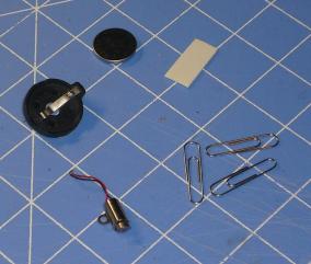
Here you can see all the parts you will need for this project.
  • 3 small paper clips
  • 1 piece of double-sided foam tape
  • pager motor with weight attached
  • 1 coil cell battery holder
  • 1 3V coin cell
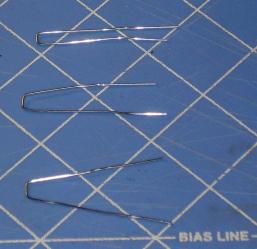
After gathering the parts, We need to make the legs of the robot. First, straighten the 3 paper clips. They don’t have to be perfect, just straight-ish.
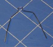
Next we need to bend each paper clip in the middle. This helps the legs stay at the correct angle later. Two of the paper clips can be the same size bend (about 7mm in the middle) and one must be slightly smaller (about 5mm in the middle).
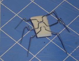
Next, bend the long parts of the paper clips outward. The paper clip we bent to 5mm is on the bottom in this picture.
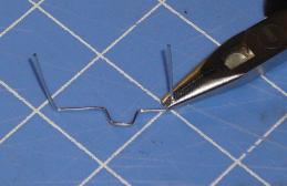
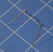
Now bend the paperclip we bent to 5mm into the shape shown. This makes the front legs of the robot.
If you want, you can make the bend go up, then back down as shown here. This will add to the bug look and make it easier to make all the legs even later.
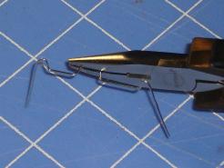
Now bend the second paper clip up to form the legs.
Again, a “kick” in the bend might make it looks more buggy.
Now bend the last set of legs. It helps of you angle them a bit as shown below.
Now place the legs on one of the stick sides of the foam tape as shown here. We’ll adjust the lengths and angles a bit more later so for now, approximate placing is ok.
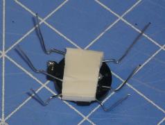
Now stick this to the bottom of the coin cell holder, making sure not to cover the solder terminals. On my holder, there were little plastic tabs getting in the way, so I cut them off to make the tape lie more flat.
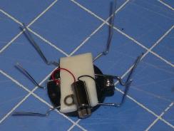
Now solder the motor to the battery holder terminals.
Now solder the micro DC motor to the battery holder terminals.
(Pls refer to jifei’s mini vibrating motor :https://www.vibrationmotor.net/product/z0612-dx/)
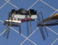
Here you can see the back and side profiles of the little guy.
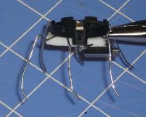
Now here is one of the most important steps! You have to adjust the legs. The robot is similar to this leg layout. Having built TONS of Stiquito kits, I know what to do here. The legs must be leveled out. Do this by standing it on the table and cutting all the legs to be even. Try not to cut too much.
Once all the legs are even, you need to bend the “feet” slightly backward so the angle is about 120 degrees. This will cause the vibration of the motor to propel the robot forward. You can see what I mean here:
Once this is done, you are ready to go. Play with the leg design a bit to see if any adjustments bring out different behaviors. You might have to tweak it a bit to get it to go straight. In my experience, it will always turn more in the direction the motor weight is spinning.
A final addition of tiny googly eyes makes this robot complete. Have fun and enjoy!
                                                  With Love
                                         www.vibrationmotor.net

2017年4月5日星期三

How to Build a Vibration Motor Circuit

How to Build a Vibration Motor Circuit

Vibration motor 


In this project, we will show how to build a vibration motor circuit.
A vibration motor is a motor which vibrates when given sufficient power. It is a motor that literally shakes.
It is very good for vibrating objects. It can be used in a number of devices for very practical purposes. For example, one of the most common items that vibrate are cell phones that vibrate when called when placed in vibration mode. A cell phone is such an example of an electronic device that contains a vibration motor. Another example can be a rumble pack of a game controller that shakes, imitating the actions of a game. One controller where a rumble pack could be added as an accessory is nintendo 64, which came with rumble packs so that the controller would vibrate to imitate gaming actions. A third example could be a toy such as a furby that vibrates when you a user does actions such as rub it or squeeze it, etc.
So vibration motor circuits have very useful and practical applications that can serve a myriad of uses.
To make a vibration motor vibrate is very simple. All we have to do is add the needed voltage to the 2 terminals. A vibration motor has 2 terminals, usually a red wire and a blue wire. The polarity does not matter for motors.
For our vibration motor, we will be using a vibration motor by Jifei Holding Limited. This motor has an operating voltage range of 2.5-3.8V to be powered.
So if we connect 3 volts across its terminal, it will vibrate really well, such as shown below:

Vibration motor circuit
This is all that is needed to make the vibration motor vibrate. The 3 volts can be provided by 2 AA batteries in series.
However, we want to take the vibration motor circuit to a more advanced level and let it be controlled by a microcontroller such as the arduino.
This way, we can have more dynamic control over the vibration motor and can make it vibrate at set intervals if we want or only if a certain event occurs.
We will show how to integrate this motor with an arduino to produce this type of control.
Specifically, in this project, we will build the circuit and program it so that the motor vibrates every minute.
Parts Needed
  • Arduino Board
  • Vibration Motor
  • 1N4001 Diode
  • 0.1µF ceramic capacitor
  • 1KΩ Resistor
  • 2N2222 NPN Transistor
  • USB Connector


The vibration motor we will use is the shaftless vibration by Precision Microdrives. This can be obtained from Jifei at the following link: Jifei Vibration Motor. .
The vibration mechanism and all moving parts are protected within the metallic housing encasing of the motor. For sturdiness and strength, the wires are reinforced and there is a 3M adhesive on its back surface.
The motor will vibrate considerably when supplied with 3V.
The datasheet for this vibration motor pls contact: info@vibrationmotor.net for detail.
Almost any NPN transistor can be used to provide current amplification. If you do not have a 2N2222 NPN at hand, then substitute it for a 2N3904.

Vibration Motor Circuit

The vibration motor circuit we will build is shown below:

Arduino vibration motor circuit
The schematic diagram for this circuit is:

Vibration motor circuit schematic
When driving a motor with a microcontroller such as the arduino we have here, it is important to connect a diode reverse biased in parallel to the motor. This is also true when driving it with a motor controller or transistor. The diode acts as a surge protector against voltage spikes that the motor may produce. The windings of the motor notoriously produce voltage spikes as it rotates. Without the diode, these voltages could easily destroy your microcontroller, or motor controller IC or zap out a transistor. When simply powering the vibration motor directly with DC voltage, then no diode is necessary, which is why in the simply circuit we have above, we only use a voltage source.
The 0.1µF capacitor absorbs voltage spikes produced when the brushes, which are contacts connecting electric current to the motor windings, open and close.
The reason we use a transistor (a 2N2222) is because most microcontrollers have relatively weak current outputs, meaning they don't output enough current to drive many different types of electronic devices. To make up for this weak current output, we use a transistor to provide current amplification. This is the purpose of this 2N2222 transistor we are using here. The vibration motor needs about 75mA of current to be driven. The transistor allows this and we can drive the motor. To make sure that too much current does not flow from the output of the transistor, we place a 1KΩ in series with the base of the transistor. This attenuates current to a reasonable amount so that too much current isn't powering the motor. Remember that transistors usually provide about 100 times the amplification to the base current that enters through. If we don't place a resistor at the base or at the output, too much current can be damaging to the motor. The 1KΩ resistor value isn't precise. Any value can be used up to about 5KΩ or so.
We connect the output that the transistor will drive to the collector of the transistor. This is the motor as well as all components it needs in parallel with it for protection of the electronic circuitry.
Now that you understand why we use all the components which we do, let's go to the code that allows the motor to vibrate every minute.

Vibration Motor Code

The code that vibrates the motor every minute is shown below:

Code to vibrate the motor every minute
const int motorPin = 3;

void setup()
{
pinMode(motorPin, OUTPUT);
}

void loop()
{
digitalWrite(motorPin, HIGH);
delay(1000);
digitalWrite(motorPin, LOW);
delay(59000);
}
The following code, again, vibrates the motor every minute for 1 second of a duration of time.
The first line of code declares that the motor is connected to arduino pin D3.
The second block of code sets the digital pin D3 as output. This output represents the motor.
The third block of code turns the motorPin HIGH and delays it 1000ms. This represents the motor turning on for 1 second. The second half of this block then turns the motorPin LOW and delays it 59,000ms. This represents the motor being shut after being on for a second and staying off for 59 seconds. So, in total, the motor turns on every minute for 1 second of time.
This is just one type of circuit that can be built. There are many variations which can be done, including the motor shaking when a certain action is done such as noise being detected or motion being detected. With a microcontroller such as an arduino, we have more control.
Also note that the 3.3V terminal on some arduinos may supply enough current to power the vibration motor. So you may be able to run this same circuit without the transistor setup. However, if you are powering multiple motors (in parallel), then a transistor may then be absolutely necessary.

With love
www.vibrationmotor.net

2017年3月29日星期三

PCB-mounted Vibrator Motor

PCB-mounted Vibrator Motor

lag:SMD motor,SMT motor,PCB mount motor,mini PCB motor

JiFei Holding Limited would like to  introduce a micro-sized PCB-mounted vibrator motor https://www.vibrationmotor.net/pcb-mounted-vibrator-motor/ which based on a surface-mount form factor, and suitable for use in many handheld appliances and instruments to u.
This SMD vibration motor can be reflow soldered and comes on tape and reel for quick and efficient pick-and-place assembly.
A new addition to Jifei’s range of Pico Haptic miniature vibrating motors, it offers a tiny PCB footprint and an efficient mass-assembly method.
Micro-sized vibrator motors such as the 304-109 are used in many handheld appliances and instruments where there is a requirement to alert operators and users that an event has occurred.
Termed ‘operator/user alerting’, the vibrator motor has much the same function as an LED, lamp, buzzer or audio alarm.
The benefit of using vibration motors in this way, and vibration-tactile feedback in general (also known as haptic feedback), is that it works in scenarios in which users can’t see or hear the device.
The silent profile in cell phones and pagers is an example of where vibration tactile feedback warns users in a wide range of situations, no matter where the device is actually located.
Jifei  produces a wide range of vibrator motor form factors in miniature scales from 4mm through to 12mm motors that are easy to integrate into designs.
Jifei’s range offers PCB-mounted vibrating motors, including spring and pad vibration motors, reflow surface-mount motors and thru-hole pin and flying-lead vibration motors.
We also produces self-adhesive mounting coin vibration motors, as well as motors designed with rubber surrounds for easy mounting within enclosures.
The 304-109 surface mount vibrator motor has an external footprint of 4.5mm wide, 13.6mm long and 4.5mm high and weighs in at 0.95g.
This 4mm coreless cylinder motor is based on the same proven technology as the other 4mm, 6mm and 7mm types offered in the Pico Haptic range of micro vibration motors.
The SMD vibrator motor, rated at 3V DC, runs at a nominal 12,000 RPM (200 Hz) while generating 0.6g (5.88m/s) of vibration.
Based on a coreless three-pole design, the motor has a certified start voltage of 1.4V.
Typical current draw is 70mA and the motor has a typical vibration efficiency of 2.7g/W.
With a typical noise output of 50dBA, the motor is quiet for vibration standards and has a standard operating temperature of -20C to 60C, though these can be extended by request.
The motor comes via either cut-tape or as standard package size of 1,000 pcs on a 330mm reel.
This vibration motor is designed for pick-and-place and reflow RoHS-compliant soldering processes.
With Love
www.vibrationmotor.net

2017年3月19日星期日

Coin Vibration Motor Failure Analysis

Coin Vibration Motor Failure Analysis


Problem:

When the motor is installed, the vibration failure and not vibrating.


Analysis:


1.Recheck and confirm:
The performance review found that feedback motor have the rotor wire breaking phenomenon (i.e. rotor two coils with a hard line OK, another hard coil and open circuit phenomenon)which determine the performance of motor NG.

2.Disassemble inspection: (Main motor parts:up case,down case, rotor)
Disassemble the motor and inspect the rotor circuit:
1 feedback motor rotor testing (P1) into a 37 ohm resistance line detection OK (P2), the two resistor resistor of 4.7, coil and hard line disconnection (P3)


        P1                          P2                          P3

Summary: 

Through the analysis of the performance inspection and disassemble, analysis personnel to determine the rotor broken is the result of motor performance when vibration is not the main vibration


Reason analysis:

1, the cause of poor motor working principle of vibrating motor is energized by current due to contact between brush and commutator of the current flowing into the coil, coil and stator magnet formed cut magnetic lines, so as to generate electromagnetic force, the electromagnetic force of the rotor rotor. A feedback coil motor rotor is broken, another coil line OK, the motor will appear when the brush and the commutator coil is connected with a good connection when the motor vibration, when the brush and the commutator coil wire connection motor vibration phenomenon. When the motor vibration is caused by vibration.
2, causing the rotor broken motor outflow reason: our resistance of the rotor is full inspection, the rotor does not exist disconnection normally under the stream, in addition to the motor rotor assembly after our performance and semi-finished products and finished products inspection inspection process, the motor will not break the phenomenon of outflow will exist. Analysts believe that the feedback motor thread breakage is due to coil coil welding welding workers, no coil and H-PCB coil with H-PC welding, weld phenomenon, cause the motor in operation after a period of time, a coil and a H-PCB connecting line. In the inspection personnel to check the motor, when the coil is connected with the brush and the commutator good connection, motor vibration, when the brush and the commutator coil connection is disconnected, the motor vibration and vibration when the motor is bad, no vibration phenomenon.


Improvement measures:

1, to strengthen staff training and education of the rotor coil, avoid the defects of weld, welding sparks coil.
2, strengthen the training and education of motor performance testing personnel, while strengthening the supervision of motor performance testing process, to avoid false detection, omission phenomenon.


With love
www.vibrationmotor.net


2017年3月13日星期一

Haptic Feedback Motor

Haptic motor

Haptic feedback motor is a kind of intelligent vibration motor, according to different application scenarios, allowing users to feel a different sense of shock, and can subtly produce different subtle vibrations in different position on the touch screen. The haptic feedback motor allows the user to interact with the electronic products in a more in-depth manner, simulating a more comprehensive virtual environment

FEATURES

  • More vibration effects.
  • Facilitate the process of prototyping.
  • Easy-to-use library with 123 kinds of vibrating modes.
  • Powerful driver to implant more advanced functions.

APPLICATIONS

  • Mobile phones and tablets.
  • Wearable devices.
  • Remote controls, touch-enabled devices.
  • Industrial human-machine interfaces.
with love
www.vibrationmotor.net
2017年3月9日星期四

The difference between a linear motor to a bar motor or coin type motor

The difference between a linear motor to a bar motor or coin type motor

At first, the smart mobile phone is mainly used to provide feedback to the user's voice, and later with the mobile phone software is more and more abundant, the user experience on the use of increasingly high demand, use sound to provide feedback has been unable to meet the demand of users of intelligent mobile phone. As a result, part of the smart phone began to use the motor to provide vibration and touch, but with the increasingly thin cell phone, the traditional rotor motor can no longer meet the new requirements, so the linear motor came into being.
And what's the difference between a linear motor and a tradtional bar motor and coin type motor.
Pls refer to as follows:
We can find that the linear motor can make the user feel different vibration sensation according to the different scene, and can send out different subtle vibration on different positions of the touch screen.
And long life time but little current consumption.
It will be the best choose for smart phone.
                                    with love
                                     www.vibrationmotor.net